Resonators on North American Marimba
By Jim McCarthy | October 10, 2011
One of the main differences between building a marimba in North America and making marimbas in Australia, is in the resonators. The materials available are simply a little different. That is one of the main reasons that I explain the principles in the building guides as well as use specific examples – to allow for some variations. In building this P524 marimba in Canada though, I wanted to show how one can overcome some of the common potential issues!
The first issue is simply that of different types of pipe commonly used. Mostly throughout North America, plumbing is not in fact done with PVC pipe at all, but with Black ABS pipe which is softer and more importantly has a thicker wall. Because the resonator and the bar are best matched when internal diameter of the pipe is roughly the same width of the bar… this creates a problem. By the time you add the wall thickness to the internal diameter… THEN also add the thick wall of an end cap, the whole thing ends up to wide and the bottom of the resonators don’t fit in the space. I’ve seen people come up with all sorts of time consuming solutions for this, but there are easier ones! So here goes!
 The top two octaves of a five octave marimba use 1 ½ inch pipe. The metric standard is 40mm – and both are available generally in North America but only in that thicker pipe. The solution here is simply to not use standard caps for this pipe, but to use instead the thin plastic “test caps”. These work just fine and in fact look even better than normal thin wall caps when painted up nicely. Because the plastic is so thin though, it can be tough to accurately produce a tone by striking these on the end of the higher tubes though. This means that a few more than usual need to be “passively tuned” – ie tested for good resonance under the finished bar, rather than tested with a tuner or stroboscope. The photo here shows some high resonators using these test caps – sometimes they come in orange colour also.

This photo here, basically shows the next two octaves down C#3 to C5 use 2 inch pipe. Here’s the super easy solution! You CAN GET THIN WALL PIPE IN 2”!! Even in a basic hardware store like Home Depot thin wall pipe is readily available with perfect end caps to suit. BUT don’t lok for it in the plumbing section. Look for it in the section that deals with ducted vacuuming systems – that’s what this type of pipe is used for in America and Canada. Using this solves the space problem, and is a whole lot cheaper and lighter to boot!

Shown here are two specific problem notes… C3 and B2. On this marimba they are on the end of the middle row of resonators. In Australia I simply use a 60mm PVC pipe for this which Is a medium wall thickness, and although not as common as others – still reasonably available and inexpensive. In the small city I was building in though in Canada… I could find virtually NOTHING between 2 inches and 3 inches that would do the job. Now actually you could get away with using just the same 2inch vacuum pipe for these two notes, but the bars ARE just a bit too wide and I like to match things up properly. SO I found this solution here… which is a 60mm electrical conduit. I could not find caps to suit, so for these two tubes I will have to make internal plugs – a pain – but it means the pipe is well matched. As this pipe has a thick wall, caps would likely take up too much space anyway.
 This photo here shows the bottom row of resonators – the big ones! The highest of these was no major problem. In Australia we have a very common and cheap PVC pipe that is 75mm (3 inches) in diameter. It is used for stormwater and is very thin wall and the 90 degree fittings are very tight turns. Now mostly in North America, the black ABS is standard for 3inch pipe BUT you can get a thinner wall white PVC. It is even labelled with the metric 75mm! Admittedly I could only find this pipe in one of the major stores in the city I was in… but I have seen it in other American cities a fair bit. The Home depot stores I looked at had the fittings for the PVC pipe… but not the pipe!! Crazy!

There was still a small problem though because the 90 degree bend fittings available are different – they are more like pressure pipe fittings and do not turn so tightly. This means that when you put them together they make a wide U bend that might not fit under your instrument without hitting the frame. My solution was twofold – firstly the frame modification to use a single lower strut – (read the last blog entry). Secondly, I made these fittings a fraction shorter by sawing the joining area in half on the two bends before gluing them. You can see from the close up photo here that the extra inch that it gave me in room was just enough!
 The bottom resonator on the prototype was a 4inch (100mm) pipe – and this pipe is available in both ABS and PVC generally. As it is just the bottom note you have a little flexibility in room because you can always shift things over a little – so it doesn’t matter much what you use. Actually I ended up using this pipe for the bottom tube on the other row also – the C#2 – as it helped solve an issue there which I’ll write about below. The bends on this pipe were not very tight either, so I repeated my trick of sawing away some of the join area. Even so though, there was no way I was going to be able to neatly fit this tube with the bend going inwards… so for this bottom resonator I went towards the player instead, and angled just a little outwards – it comes just inside the frame so I’m happy. The C# is not fitted yet, but I anticipate it fitting ok with the bend going the normal way because there is a little more room to twist it towards the frame end – it does after all start half a bar width further up!
 This left still a couple of resonators in the middle of this bank that would normally be made with 90mm pipe. In Australia, 90mm is another stormwater grade so cheap and easy and tight bends. I could not find ANY pipe though that would really do this job – what is needed is something in between the 4 inch and the 3 inch pipe. There just wasn’t any where I was buying! My solution was to use the 3 inch pipe which at least fit.. BUT I made sure that the mouth end of the tubes under the bars.. was the flanged bits that come at the end of a whole length of tube. You can see in this photo here that the top sections of two tubes are wider. This is not ideal, but it does at least correctly match the impedance of the tube mouth to the bar – and with the thicker wall tube, it does not look silly making a one inch jump in diameter for the last note on the row.
ONE more thing I wanted to do differently with this marimba.

Normally I use sealed rivets to construct the resonator banks, but it seems these are not popular the world over. In most major cities etc in the USA and Canada they are reasonably available BUT not so much in Saskatoon where I was building this one. I could have purchased them online or chased some down probably, but I wanted to find an alternative. This is what I used shown here in this photo. Short screws designed for sheet metal. I needed to drill holes for these that were a little smaller than the screw size – that way they grip well and make an air tight seal going in. The down side of this is that there are sharp points inside the top of the tubes which could grab your fingers when dismantling the instrument – so I am going to find a small grinding wheel for the end of my drill, and grind these reasonably flat to the wall of the tube – then they will be safe and look neat!
Topics: Uncategorized | No Comments »
Building A Modified 5 Octave Marimba in North America
By Jim McCarthy | September 24, 2011
Hi all
Well the American Summer of 2011 saw me spend about five months in Saskatchewan, Canada. And as I now plan on doing this on a regular basis, it seemed only natural that I needed to make a marimba for use here – certainly you can’t just pop a five octave marimba in your suitcase every trip! So I started building one using my P524 design in the last couple of months – just in a slow way in spare time. Unfortunately I had to get on a plane and head back home to Australia before had a chance to finish, but I will finish the instrument right away when I return in 2012.
In the meantime – here are a couple of blog posts to show some of the modifications I decided to use. Some of these are just because they are a little better or simpler in some way, and others are because the materials readily available in North America differ just a little from those “back home” in Australia. This never really presents any big problems – just means a few alternatives had to be used.

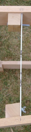
This first picture shows the most fundamental modification, which is the lower support and diagonal structure of the frame. You can see that in this version of the P524, have replaced the diagonals that went from the middle area of the horizontal struts to the lower parts of the end sections…. with this – an added lower horizontal strut with diagonals going the other way – ie from the UPPER part of the end sections to the middle area of this new horizontal lower strut. This method is not structurally a whole lot stronger or anything like that – it may be a fraction more simple in the dismantling and set up though and has less risk of breaking the diagonal structures whilst setting up. The original design was fine when bolted together but was a tiny bit at risk when dismantled. THE MAIN reason for this modification though was actually to provide a bit more room for the resonators at the big end as they bend at the bottom. You will see more about this in the next post… but I realized that the bends I had available in the PVC pipe were bigger than the ones in OZ, and took more room!
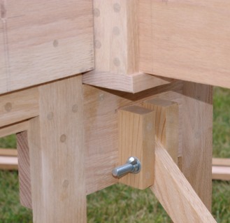
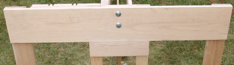
These two pics show the detail of the diagonal at the big end. Note how an extra bit of timber is positioned between the two middle verticals – this is where the top of the diagonal is bolted.
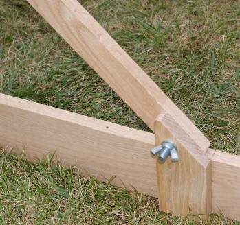 Here you can see how at the low end the diagonal is simply bolted to a fitted piece on the lower horizontal. It was tempting to just bolt right onto the side of the horizontal itself… but doing it this way meant the lower horizontal and the diagonal could both be perfectly in line and on the exact centre line of the instrument frame.
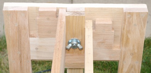
 This photo shows the slightly wider timber blocks I’m using on the bar support struts that the aluminium resonator support pieces are bolted to. This method was not the one originally outlined in the P524 building guide, but the guide did suggest it as an alternative. I decided to use it here. It looks a fraction chunkier, but it DOES have a couple of advantages. Firstly it only requires a SINGLE timber block on each of the outer strut connection points rather than two – and secondly it allows the use of standard imperial bolts with wing nuts which are cheaper and easier to use than the allan key bolts.
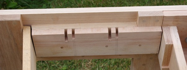 At the big end of the frame, I’ve replaced the fully height adjustable mechanism for the lower resonators with the tried and trued slots. You can see I’ve used two different depth of slot calculated carefully to cater for the likely variations in playing temperature. SO The low resonators can sit at TWO different distances from the bars… but this method is a lot faster and simpler to make, and is much less prone to creating phantom creaks and movement in the resonators!
 At the top end of the frame, the design is really the same… but you can see from the picture that rather than have a block of timber between the horizontal struts, then ANOTHER smaller block to go between the resonator struts…. I’ve made it all from a single piece. It just looks a little neater and leaves less screw holes to fill!
This whole frame is made of nice hard oak – a great frame timber as it tends to resist and suppress vibration – it sucks for bars but that is perfect for a frame! Compared to similar timbers in Australia this was actually pretty inexpensive and all easily available from the local Home Depot store. Some of the sizes are a little different from the original spec – but there was little thinking involved as the guide had allowed for this, So I could just follow my own advice and instructions from the guide on these modifications! So all in all this frame building was a pretty quick process!
Topics: Uncategorized | No Comments »
P524 Concert Marimba Building Guide Completed
By Jim McCarthy | November 26, 2009

Hi all! – well the day has come at last – finally the building guide and all the instructional videos for this P524 marimba, are finished and now available to all.
Everything you need to build this exact instrument, or a marimba with any range from five to four octaves. All the information required for even a complete beginner to build a profesional concert marimba that sounds every bit as good as a commercial model – or even better. The guide is over 170 jam packed pages with over 800 photographs and diagrams. There are five videos included with almost two hours of content showing all the details of bar tuning techniques.
To find out detailed information about the guide, go HERE.
Topics: Uncategorized | 7 Comments »
Finishing the 5 Octave Marimba
By Jim McCarthy | July 14, 2009
This week saw me finish things up on the Five Octave Marimba project. Actually there are a few more things I will do slowly over the next few months, as I discover some of the subtlties of this particular instrument – BUT I have now arrived at the point where I can actually play the marimba – and it LOOKS really great too! Here’s what this post will cover:
- Getting the wheels on.
- Finishing all the horizontal struts with felt strip and bar posts.
- Trying some different strings and stringing the bars.
- adjusting resonator height.
- Testing and making small adjustments.

With all the woodwork protected by estapol, I could finally screw the castors onto the bottom of the frame. The particular wheels I’ve chosen were quite expensive but I wanted these ones as the quality is very good and they also have a good combination of a base plate small enough to screw on to the frame without TOO much extra timber just for that purpose – AND – a decent size actual wheel. Small wheels are not much use on a marimba of this size unless you are only ever rolling it along a super smooth glass-like surface – yeah right! These ones will work fine on carpet or concrete surfaces without vibrating themselves and the instrument to bits. It also helps that they are made from a hard rubber compound which has a slight suspension effect. These wheels came in a version with and without a locking mechanism. The ones with were more expensive, so I got two of each. The idea is that you really only need one locking wheel at each end of an instrument to hold it firmly in place. I was careful to make sure the wheels with locks went on the side of each frame end that would end up closest to the player. This means that the locks can be kicked on and off by the performer without moving out from behind the instrument.
The other task needs to be done AFTER the estapol goes on, is putting all the string holding bar posts into the timber struts. I touched on this in the last post, so you can check out the details there. This week however saw me have the time to actually finish the process with all four struts. In total it’s almost 150 bar posts so it takes more than a few minutes!Then the joyous moment – time to string the bars! This photo to the left shows the top bars loosely strung into position. Notice how the string goes around the two brass support posts at the end. Notice also that I’m stringing the “white” notes first. This may seem obvious but it certainly is easier this way and I’ve seen people try it the other way!

This photo to the right shows the bottom bars strung up. At first I used a double plaited 4mm nylon cord which is actually called “starter cord” – the sort used on lawnmover pull starts. I often use this as it is really strong and durable and it also has the added bonus that you can work it with a flame to melt it. This means it’s easy to tidy the ends and prevent fraying, but more importantly you can mend it quickly! I carry a cheap cigarette lighter as part of my small gigging repair kit. If a nylon cord breaks it makes the instrument unplayable, and in the middle of a show it takes too long to re-string a set of bars even if you happen to have a spare lengthy of cord. Thats where the cigarette lighter comes in. You just trim the cord ends where it has snapped, then melt the ends together using the flame. You may have to adjust the cord a little to make up for the missing length and ensure the join is not in a position where it interferes with a bar’s vibration – BUT it is a quick fix which works really well.Unfortunately for me, I was unsatisfied with the result using the nylon cord in this particular instance. The reason was that some of the bars made a slight rattle or buzz on the cord when it was strung tightly. This is a reasonably common issue. It tends to happen more on bars where the natural nodal lines don’t match up perfectly with drilled holes – as is common – but in general it can happen anyway. Sometimes it can be just a bit of a click sound on the initial impact of the note – caused by the inside of the hole striking the hard surface of the cord – but still undesireable. Strangely enough I have found that this tends to happen more on bars with holes that are drilled really well – those holes that have a bit of a bend in them hold the cord a little and don’t buzz. Of course the downside is that they also can choke the vibration a little as well. Using a smaller diameter hole through the bars can help this problem as well as there is less room for movement on the cord. Obviously I can’t make the holes smaller at this stage, and in any case I made them the size I did for a good reason. That little bit bigger means the bars are easier to string and also that they are a little more free to vibrate. This really plays a crucial part of the instrument’s sustain.
So my solution was one I’ve used many times before – I changed the cord to a 4.5mm plaited cotton variety. This is called “sash” cord or “venetian blind” cord. It comes in various diameters but you don’t want one actually big enough for a window sash! The 4.5mm is just big enough to fill up a little more of those holes in the bars. More important though is the fact that it is made of cotton. Even under high tension the cotton cord does not have a hard exterior surface like the nylon does. This acts a bit like felt would – it dampens any hard contact sounds. The photos here actually show the cotton cord in use. With the bars restrung with cotton, all the problems went 100% away. Great! Notice the spring between the tension posts at the bottom end of the instrument. This keeps tension on the cord as well as makes it easy to remove the bars without untying anything.

Here we see the finished instrument! Looks pretty good I reckon. The next step was to make some minor adjustments. Firstly I adjusted the resonator height at the low end to best suit the room. This will change from venue to venue as temperature changes. It was only a subtle difference as the starting height was pretty close to as good as possible for “normal” condidtions – as intended. For more extreme temperature conditions the adjustment will be useful. It’s easy to do with this cool system I made which you can see in the photo above right, and just involves twiddling a couple of screws with the allan key. It’s a simple listening test. Hit a couple of low notes – adjust height – hit same notes – compare sound. Do this a few times till you arrive at the best sound.The next step was to play each note a few times. A couple of notes were sounding just a little muted owing to their bar posts being slightly off position and pulling the string firmly against the side of the bar’s hole. It is a small imperfection, but one worth fixing. One of the reasons I prefer making my bar posts from aluminium rather than steel, is that it makes these things easy to adjust. I went over every post with a screwdriver and small hammer giving them a tiny tap one way or another to make sure the cord came through the center of each bar’s hole and into the middle of the bar post’s slot without any sideways tensions at all. This made sure all the bars were perfectly free to vibrate fully with no muting from the string at all. Once again – it’s worth mentioning that I’m talking about very subtle improvements here, but why not?

Here we see the view from the audience side of the marimba. Notice how the dummy resonators at the low end hide all the bends and twists in the tubes behind them.I’ll post some more info for you later on down the track, but for now this five octave marimba is finished and ready to enjoy! All that remains to be done is to write up the building guide and finish the instructional videos so YOU can easily make one of these marimbas yourself. This will take me a little while, but put your name and email address in the box at the top right of this page, and you will get a couple of email updates along the way. Don’t miss out on the super deal I’ll be offering the earlybirds when the building guide is launched!
Topics: Uncategorized | 8 Comments »
Making the Marimba Look Nice & Stringing the Bars
By Jim McCarthy | July 9, 2009
Welome back marimba building enthusiasts! In this installment of the 5octave marimba building blog I’ll go over some details of the final stages. I’ll cover:
- Staining and coating the frame with estapol.
- Spraypainting the resonator banks – you won’t believe they’re not metal!
- Using felt lining and rubber tubing to keep all the joints rattle and squeak free – you hear JUST the marimba!
- A better and faster way to produce the aluminium bar posts so that they look completely professional.
- Putting the bar posts and string tension posts into the horizontal struts, and putting on the protective felt strip.

The painting of frame and resonators is a time consuming task. It takes a while to do anyway, but then there is also drying time to consider and the fact that everything needs more than one coat. The resonators in particular caused mean issue because it is not summer here at the moment. As I have to spray paint outside, this means I am at the mercy of the weather quite a bit. It needs to be warm enough for the paint to stick well and dry properly in reasonable time,and it also needs to be fairly wind free conditions to have any hope of getting the paint where you want it. It took me about a week to get the resonators done even using paint which could be recoated within the first hour of drying. The basic idea is to lay out all the resonator banks on a flat surface – in my case on a large sheet of plastic so overspray would not paint my tables underneath. Then spray a first coat over all the surface possible. You wan’t to get as much paint on there as you can without it running in drips – better to have morecoats than a bad job. It can be tricky to get paint into the gaps between the tubes,so it is usually better to start spraying into the gaps fromone side then the other before spraying the outside facing faces. The paint I was using allowed a recoat withing the first hour or after 8 hours, so I was sure to come back about 45 minutes after the first coat and thicken it up a little. The next day I turned the resonator banks over so that the unexposed bits were now showing, and repeated the process.

Because of the shape of the banks, some of them needed to be coated from three or four different angles to fully cover all the visible surfaces. I also like to spray quite a bit inside the tube mouths as this makes them look a lot better from the top – even with the bars in place over them. Once all the surfaces were covered, quite a few of them needed another coat. One thing I have learnt doing this task over the years, is that the quality and type of paint you use plays a major part in the result! Better paint can be more expensive, but it is usually well worth it. It sticks better, dries better, looks better and usually wears better as well. By this I mean that it won’t chip and scrape off with the slightest touch. I have also found that a coat of plastic primer can help this stickability when painting plastic pipe, so I gave all the banks a coat of this stuff here in the photo before the paint.

The timberwork was not so much of a problem, as I was brushing it on. This meant I could do it indoors as long as there was decent ventilation. I also wanted to stain the frame timber. Partially because I just wanted a darker, browner colour to contrast more with the reddish colour of the bars, but also because the timber of the frame varied in colour quite a bit. I used Australian Oak for some bits and Meranti for others. These were quite different, but even the Meranti planks provided quite a variety of colour in themselves. SO…. To both save time and help with the colour differences, I used a 2 in 1 estapol stain product. I like this product for this job, as it has a way of putting the colour on top of the surface rather than soaking into it – particularly on the second coat. This means it tends to bring the different colours closer together. Of course it also means there is one job not two. Great! You DO have to be a little more careful in the application though to avoid streaking and blobs of colour. You need to brush everything very evenly. After a first coat, a light sand with fine paper prepares the surface for a second coat which goes on smoother and darkens the colour further. You can see the result in the photo here. I’ve used a satin finish rather than a gloss finish here as it tends to be more forgiving looks wise of the odd scratch etc. It’s probably a good idea to put a third coat of estapol on any parts which will wear particularly. I like to use normal clear estapol for the third coat,as it means that if it DOES get a little scratch or scrape then it is not taking the stain colour away and is less visible.

After all the timber parts were dry, the next step was to glue on some bits of thin felt to the surfaces that would be touching each other when assembled. This is particularly important at the ends of the more diagonal horizontal bar support struts as they tend to be bounced direcly when playing, but unlike the inside struts in this particular design,they are not actually held firmly to the end sections with bolts – they just rest there. I also like to line the parts that ARE bolted together anyway – it doesn’t take long in the scheme of things when you consider the time spent overall. You may actually remember from previous blog entries, that when fitting the struts to the frame end pieces at various points in the construction, I left a little extra room to allow for the thickness of this felt which I had already purchased in advance, so I knew how thick it was exactly, and so knew how much extra gap to allow.

The resonators are also prime candidates for causing squeaks and rattles – mostly at the points where the ends of the banks meet each other and/or the supports that hold them up.The most effective solution in this case is to stretch some thin and soft rubber tube over the ends of the aluminium flat that form the ends of the resonator banks. This isolates them from each other, and also from the supports in one step. Once again – I had my specific tubing sorted out before I started construction on the marimba, so I knew how much thicker it would make the aluminium strips at the resonator ends. This was important, as the slots for them had to be cut out from the aluminium cross supports.Also the ends of the resonator banks needed a little bend in some cases to tweak them to the perfect gap so the smaller banks would fit neatly inside the bigger banks. See the photo here. Also of course at the small end section of the frame, the little timber block needed to be cut allowing for this tube also.Now normally, my first port of call for rubber tubing and similar things, is my local rubber supplies shop which stocks just about everthing . In this paricular case however there didn’t seem to be anything available in a soft walled tube that was big enough to go over the 25mm wide aluminium – or at least that wasn’t way too thick. I searched online and did find a place that sold larger diameter silicone tubing with a thinnish wall,but it was REALLY expensive and had to be shipped from overseas as well. The solution in the end was simple and cheap. The local bike shop sold me an inner tube – the sort I used to get punctures in all the time! I found the correct diameter tube and it cost me $6.50 – one tube was more than enough for the whole job.

Now it was time to get all the little string holding bar posts fixed into the struts. Actually – although I had already made a few of these using nothing but a drill and an angle grinder, I wanted to make the rest a faster and better way. For those who don’t have access to more expensive workshop machines, the simple method shown in one of my previous posts actually works quite well,and you get reasonably fast at it. Theres about 150 of them ona 5 octave marimba though, so it’s worth using a good process if you have it available to you.

The photo here above left shows a superior way of cutting the round ended slot that the strings sit in – using a milling machine with a 4mm mill bit. It is a simple matter of measuring and marking the point where the slot should end,then setting up the clamp so the aluminium strip is centered on the bit. The mill then only has to travel in one direction to cut a single short slot. You can see from the photo of the finished product to the right, that the mill cuts a really nice and uniform slot with straight sides and smooth edges – no rough bits. The cut outs at the bottom COULD be done with the mill also, but there’s a faster way which also creates hard 90 degree shoulders rather than the rounded ones milling would leave. A band saw is the short cut! Milling would leave a better finish, but I opted for the faster option as these bottom bits are not seen anyway – they are hammered into the timber horizontal struts.

The aluminium bar posts are not strong enough to hold the tension of the strings at either end where it bends 90 degrees and completes the loop. They are designed to hold the string up – not resist tension sideways. Soooo we need a stronger post at each end of each strut for the string to pass around. I kinda like the look of the brass alan key bolts which I used for the resonator height adjustment and cross struts, so I decided to use these for the end posts. This also adds a look of consistency to the whole affair. These are simply hammered gently into holes drilled into the struts with a little glue to hold them in place. You can see one of them in the photo here above left.

This photo here to the right shows one of the bar posts in position on a strut and complete with a bit of rubber tube around it. The rubber tube is important as it is a soft layer between the side of each bar and the metal of the bar post which prevents rattles. For this instrument I’m using a continuous strip of adhesive backed felt stuck on top of each horizontal timber strut. These are not strictly needed as the bars should be held up high enough from the struts that they never touch – BUT – experience tells me that on occasion with a slightly loose string and a bar hit hard close to the string, the bar will flex down just enough to touch the strut and make a horrible clunk sound. The layer of felt prevents these clunks. A little slot is cut with scissors in the felt for each of the bar posts at the points where the holes are drilled in the struts. Each bar post is gently hammered into the holes through the felt with a little glue to hold it in. The self adhesive felt sticks on pretty well by itself but the bar posts really hold it on firmly. Each post is fine adjusted to the perfect angle with pliers before the tube is put on.

This photo to the left shows some of the results from this week’s efforts all put together. You can see the resonator height adjustments adjusted to a high position. Everything is starting to look pretty good now that the finishing touches are coming on and everything is going together in the proper positions.Next post will see me finish stringing the bars and the final steps.
Topics: Uncategorized | No Comments »
Finalizing the Marimba Resonators
By Jim McCarthy | June 29, 2009
Ok – so I’m still a week or two behind with this marimba building blog – I’m actually almost finished building now, but I’ll make another couple of posts to take you all through the processes. This post follows the last by about a week or so.
Here’s what I managed to accomplish in that week:
- Put the final bits of timber on the small end section of the frame to position the resonator banks correctly.
- Attached extra bits of timber to the lower end of both frame end sections to provide enough width for the wheels to screw onto.
- Filled all the new screw holes with sawdust putty and sanded off the excess ofter drying. I also went through the long task of rounding all the corners and generally tidying up the carpentry, then sanding all the timber pieces smooth with finer sandpaper ready for estapol.
- The BIG job of the week – putting all the resonators together into six “banks” rivited together with aluminium flat strips.
- I also put together the mechanism for adjusting the height of the lower resonator banks under the bars.
So lets have a look at some pics and processes.

This photo to the right shows the extra timber pieces on the small end of the marimba frame. These have to be cut very carefully to match the gaps and angles required. Each of the lower pieces fits between the ends of the long horizontal timber struts that support the bars. The ends of these pieces are cut with angles to match the angles that the struts meet the frame ends at. They are also cut to be just a little loose. Actually I left exactly one millimeter between the ends of these little blocks and the struts. This is to allow room for the felt lining that will prevent movement noises at the junctions later on. Also whilst you don’t want these struts to be a sloppy fit, you don’t want them to be really tight either. You need to be able to easily fit the diagonal struts in particular as they are slotted in after the main center struts are bolted onto the end sections.

The smaller blocks which sit on top, are cut to width carefully so that they will fit exactly between the ends of the aluminium flat bars that hold the resonator banks together. I actually had to finish constructing the top end resonator banks before cutting these blocks so I knew what the width was going to be. I also made them a measured amount undersize to allow for a little padding between the aluminium and the wood. This will be done later with some thin rubber tube around the aluminium.

This photo here to the right, shows the middle banks of resonators. These ones are probably the easiest to construct. You might be able to see from the picture above that the top end banks actually get a little wider on the top few tubes. This makes these banks a bit of a pain to construct. The reason is that the tubes are extremely shallow – so much so that there is not enough tube past the end cap for the full width of the aluminium bar that rivets onto it. These last few tubes actually have a sleeve made for them from an extra end cap without the end. These are cut to length so that the tubes are the full diameter of the end cap for their entire length. This makes it easier to rivet them neatly into place, but is the reason these banks must be finished before those timber blocks can be fitted. The middle banks are easy because they use all the same diameter tube pretty much, and the tubes are all short enough to require no bends. The photo here shows them without the diagonals rivited on yet which will hold all the tubes straight. Also the “dummy” resonators for the “black note” bank are not yet installed.

The photo to the left here shows some of these dummy tubes being fitted to the middle “black note” bank. Note that in this photo the diagonal is in place holding the bottom of these tubes in position. These dummy resonators are not needed at all for the sound of the instrument – after all they are not below any marimba bars – they are purely for esthetics. They fill in the gaps between D# and F# and also between A# and C#. The dummy tubes help to hide the diagonal strut and anything else behind the tubes from the audience’s point of view which might look slightly messy. The tubes don’t need the end caps either of course, but they are fitted anyway for a consistency of look.

This photo to the right shows the detail of the completed resonator banks for the bottom octave. There are a few tricky bends here. This design is created to allow the banks to fit completely under or inside the line of the timber frame diagonals. This means that the resonator banks can be adjusted a little higher and still not contact the diagonals. It also means that the resonator banks can be easily inserted between the main timber bar support struts after they are assembled onto the frame. You can see that there would have been room for the bottom tube to simply bend back up vertically inside the two diagonals, but this would have made inserting the assembly between the timber struts impossible. Notice how the lowest C# and D# have U bends which are angled away from each other so that the tube ends are inside the timber diagonal. This is possible because the C# is the lowest note of that bank, and there is a gap between the D# and the F# above it. This looks a little ugly from the front of the instrument, so there is a carefully constructed dummy tube with it’s back cut out to cover this, and the result is actually quite good looking. If these tubes were made from metal, the weight would be significantly out of balance because of all this tubing away from the main centerline of the resonator banks where they are hung from on the frame. The extra tubing would then need to be attached somehow to the framework to give them support. In this case however, the PVC tubing is quite light so the banks hang almost perfectly with no extra support at all. The tiny amount of imbalance is compensated for in the height adjustment mechanism which I devised for these banks.

With the resonator banks constructed, the next important step was to create the height adjustment mechanism for the bottom octave resonator banks. You can see from the photo here basically how it works although this is the “unpolished” version. The little timber L construction holds the end of the resonator assembly by the aluminium strut with a single bolt which allows a little pivot as the height is adjusted. Two bolts go through the L assembly which have threaded inserts so as the bolts are done up, the ends force further past the bottom edge. The bolts have rubber tips which sit on horizontal parts of the frame end section. You might notice there is also a third bolt through the top of the L assembly. This one has the threaded insert threaded in a hole in the top of the frame, so the bolt holds the L assembly down. This not holds everything secure and prevents any twisting, but because it is on the side of the resonator bank opposite the extra weight, it holds the whole bank hanging straight.


Now it was just the finishing stages to go, but before I could sand everything down ready for estapol I wanted to have all the timberwork finished which meant doing any extra work needed to allow wheels to be attached to the bottom of the frame end pieces. Without going to too much trouble. the best castors I could find for this instrument were ones mounted on a 60mmx60mm base plate which meant making sure there was a decent 60mm square surface on the bottom of each end piece to screw them to. For this I simply faced an extra plank on the opposite side of the verticals. You can see these in the photos here above and right.

The first stage of finishing was to fill all the screw head holes with sawdust putty. Even though I’d done most of these already in a previous stage, there was quite a few more – on the top of the small end section, the new bits on the bottom of each end section, and all the little blocks on the main horizontal struts. All of these got filled with putty, allowed to dry, and then sanded back flush with the timber faces with a coarse sanding disc. Then a few hours with the orbital sander and finer paper leaves all the surfaces smooth, rounded, and ready to paint with estapol. A little example of the results can be seen in this photo here.Well that pretty much takes care of that week’s spare moments. The following week will see the final cosmetic stuff like sparypainting the resonators and staining/estapol coating the timber. Also applying the finishing touches like felt pieces and the string holders.
Of course as usual I have to mention that all of this will be discussed in WAAAY more detail in the building guide which will be written up soon and available from makeamarimba.com or the building guide link at the top of this page.
Jim McCarthyTopics: Uncategorized | No Comments »
Marimba resonators and More!
By Jim McCarthy | June 14, 2009
Hi all… well last time I left you it was almost two weeks ago and I’d just got to the interesting stage of putting the marimba together. I’d tuned a few of the easier resonators in the middle octaves and layed the bars out on the basic frame structure.
The previous weekend was a “long weekend” with an extra public holiday, so I had a little extra time to play around with the next few steps. Here’s what I managed…
- I finished the experimentations with the new “clustered resonator” designs and finished the top octave of resonator tuning.
- I finalized the design for the resonators in the lower octave, and cut and tuned them.
- I finalized the nodal lines on all the bars and drilled them through – followed by the fine tuning of the bars to exact pitch and a final polish.
- I designed the “string holders” to suspend the bars and came up with a way to easily produce them “en mass” with just a drill and an angle grinder. I made a few this way to prove that you can actually do a reasonable job of it in a reasonable time which I’ll show you – I may use a milling machine in the end however as the result will be a little more refined and quicker. In the past I’ve simply had these types of pieces manufactured to dimensions for me, but the idea of this project is to create the whole instrument from basic readily available materials and tools.
- I also decided on the resonator bank “splits” – cut the horizontal support aluminium strips for the banks, and built the “cross bars” between the timber struts to support the ends of the resonator banks. These tasks seem small, but actually take up a lot of time when designing from scratch as there are some calculations to be made! Of course, if you are building this instrument later on from the plans, you will simply be able to follow the steps of the building guide.
Ok – so lets go through these things one step at a time…
What I really WANTED to do was to get on with tuning the resonators, but experience told me that for the top octave and the bottom octave, there would be difficulties. The middle three octaves are quite easy to tune, simply by hitting them on the bottom with your fingers or a mallet and using a digital tuner or stoboscope to test the pitch. I’m very quick at this these days and know the approximate length of the pipes anyway. SO what I do is simply cut them a fraction shorter, then slide the end cap off a fraction till the correct pitch is read – then mark the position of the cap on the tube with a a texta, apply the glue and make the join. It also pays to check the pitch and adjust the end cap in the ten seconds or so you have as the glue is setting to make sure it is right on.
 The top and bottom octaves tend to be more difficult to produce measurable tones from though, so what you really need is the actual tuned marimba bar to test how it sounds over the resonator. Here is a photo of me doing this type of thing to the left using my special rubber band and open box system to suspend the bar. I can move the resonator in and out of position under the bar whilst striking it and listen for the effect in amplification and pitch.
 Before I could do any of this however I needed to do the fine tuning of the bars, and before I could do THAT, I needed to drill the nodal holes for the suspension strings. You may remember I kinda mentioned this order of events in my last post. Remember I had just ruled the nodal lines over the bars? So I spent a day drilling all the bars, then fine tuning them down to the last few cents.
So now at last I could get on with my experiments for the new clustered resonator idea!
You see, the problem with normal resonators under the bars in the top octave, is that they are SO SHORT! Firstly, they have a diameter about the same as the height, so they don’t sound very well when you activate them. You cannot actually hear a pitch when you hit them on the bottom, so the only way to tune them is by testing them for effective resonance under the matching bar. This is a hit n’ miss affair which is difficult to get accurate as you are relying on the ear’s ability to detect very subtle differences in resonances. The other way which is common to get a correct resonator length, is to calculate it. Essentially this is done using the equation v=fw where v is the velocity of sound in air (at average temperature) – f is the note’s frequency – and w is the wavelength. As we are using quarter wavelength resonators the basic calculation for resonator length is: (v/f)/4. There is also a factor called the “end correction”. Essentially the effect of the confining resonator wall continues a little way past the actual end of the resonator mouth making it effectively a little longer. This means that you have to make the 1/4 wavelength resonator measurement a little shorter for it to be in tune. Officially this is calculated at 0.61r (where r is the tube radius). In practice however, it is extremely difficult to calcualate this accurately as the effect changes with proximity to the marimba bar etc.
 My cool idea to help deal with these issues was to use a “cluster” of very small diameter tubes instead of a single large diameter tube. The idea is that by using a smaller diameter you are reducing the amount of end correction. Therefore a slight calculation error in the end correction factor accounts for a much smaller percentage of the tube length and creates less variation from the correct target pitch. Of course to achieve the same volume from the resonators, the equivalent cross-sectional area must be preserved, which is why yu will need a cluster of the smaller tubes. By using extremely thin tubes, the end correction could be cut down to a amount so small as to be not worth factoring into the calculation – BUT… the problem with this approach, is that air close to the tube walls tends to resist movement because of cohesion. In a large diameter tube this accounts for a very small percentage of the total volume of air, but in a very thin tube it is actually the greater portion of the air, and the result is a resonator which produces very little sound volume. So I reached a compromise for my main tests… I used 15mm PVC pipe which strangely actually had an internal diameter of about 19mm. By using four of these together arranged in a square, I had a cluster which fit nicely under the high marimba bars and had only slightly less cross-sectional area in total than the 40mm pvc pipe normally used.
 The PVC end caps would have been quite expensive in total considering the amount needed – and also they were quite thick and would have meant that too much space would have been needed under each bar – so clearly I had to find another way to seal off one end. Ordinary wine corks ended up providing a good solution. I sanded back a cork just a fraction so it could be force a couple of millimeters into the tube, then used a hacksaw to cut away the remaining cork and sanded the bottom flat. The cork was glued into the pipe using the normal pvc pipe glue – I also found that by dripping two drops of glue into the bottom of the tube, it sealed off the cork and made a nice hard floor to the tube.
Now after a fair bit of playing around with this idea, I did in fact get some of these clustered resonators sounding really good – probably even a small fraction better than a regular resonator! The problem was that to get four of these smaller tubes tuned was taking just as long as the single bigger tube. There were still problems with tuning the smaller ones, and there were other problems as well which I considered would come up when building them into the resonator banks themselves. I came up with various solutions for these, and I may pursue this further at a later date on a different instrument – perhaps a super high pitch instrument???? – but in the end I realised that for this marimba, the standard single-tube approach despite being troublesome in the top octave, was still the all round most practical method. So I fiddled for ages with short 40mm tubes, testing them for relative resonance under the actual bars they would amplify – and eventually came up with the set for the top octave.


So now I had all the resonators tuned except the lowest few. So it was a matter of tuning the bottom octave of resonators which are the longest and actually require some design because they are too long to fit under a normal height instrument without putting some bends in the tube. Fitting them all in and having them suspended properly can be an issue, especially if you want to have resonator tubes on the wider side like myself.
 I came up with a design and tuned all the lowest tubes. The bottom C and D I tuned, but did not glue all the joints as I wanted to leave some room for later adjustments. So with all the tubes tuned, it came time to actually assemble them. Before that though I needed to decide how the resonator banks would be split – if each row of notes had one single long bank of resonators, it would be terribly difficult to dissemble and transport the instrument, so it is common to make the resonator banks in sections. For a four octave plus sixth instrument or smallet it is usually quite acceptable to simply divide each row into halves. For a full five octave instrument with wide bars like this however, that would make for sections which would not easily fit in your average family car – something I feel very strongly that a design should allow. So I split each row of tubes into three sections. Where to make the splits ended up being quite easy as the diameter of the resonator tubes changed at the points roughly a third of the instrument length anyway, so it was obvious to make them there. This has the advantage that it cuts down on bending the aluminium strips which hold the tubes together.
 I measured the distance between the timber struts at these points that I’d decided on, and cut lengths of 50mm wide aluminium flat to these lengths. I also came up with a cool way to bolt them to the timber so that there was no bits protruding up towards the bars, or more than 19mm from the timber of the struts. Also so there is no bare metal attached to the timber struts, which is a design flaw which means that during transport your nice estapol finish to the timber tends to get scratched up by the metal bits unless each piece is individually wrapped in a blanket! The design is extra good I think because in one simple structure these pieces perform both the task of providing the resonator bank support, as well as providing structural support between the timber struts and keeping their distance fixed – a needed part of any marimba design with long spans like this. You can see from the photo here that I’ve also cut the 25mm wide aluminium strips which will rivet to the top of the resonator tubes and hold them up.
 Whilst I had the aluminium grinding wheel on the angle grinder, I also tried my hand at producing a few of these string holders. As I said in my last post… In the past I’ve simply had these produced by a third party business with computer controlled milling machines – which is certainly a time saver although of course at a cost! I really wanted to show that you CAN actually make these quite easily however with nothing more than a drill and angle grinder (with a special wheel for aluminium – a normal metal wheel will NOT do it!) The photo here is my FIRST effort… NOT my best! However you can see that it will work just fine and actually look ok too. The slighly messy bit at the bottom will be embedded into the timber strut and unseen, and there will be some rubber tube over most of the rest of it anyway, so even if these are a little scratched and imperfect, it will not really be visible.
Well that was pretty much the result of that long weekend and some bits from the week. Since then I’ve had almost another week and I’ll post about that pretty soon, so keep watching!
Topics: Uncategorized | 8 Comments »
Marimba nodes, frame & resonators
By Jim McCarthy | June 4, 2009
Hi all – it’s been just over a week since my last post, and I’ve managed to put together just a few hours this week to work on the 5 octave marimba project. Progress has been a mix of straight forward “business as usual” work for fast progress, and experimental playing around to develop some exciting brand new techniques. I’ve been thinking about these for years now, and finally this project provides the perfect time to work out the details and get them implemented.
Firstly a little more progress on the frame… After some careful measuring and bar layouts, I worked out the best position for the longer more diagonal horizontal support struts. It is a matter of positioning the bars where they need to be, then finding the best “average line” for the diagonal strut so that it lies under as many of the exact nodes as possible. The process takes quite a while, but the end result is really important – the diagonal struts can be cut, and the outer vertical legs on the big end section can be positioned and attached. Below is a photo of the result.

After that step, I put in some basic grunt work on the frame carpentry. This was cosmetic stuff. Firstly mixing PVA glue with sawdust generated by sanding scrap frame timber to form a similar colour timber putty. This was used to fill any tiny gaps in the joints and the holes left by the countersunk screw heads. The putty needs to be left “proud” to allow for shrinkage when drying, then sanded back. I also put in some time in general with the disc sander and orbital sander to clean up all the joints and surfaces – sanding them smoother and rounding out the hard corners. The result is hinted at in the photo below.

I also found time to start cranking up the next major stage of building – the resonators. In order to do this I needed to finalize some design details, then go shopping! I purchased a bunch of stuff I knew for sure that I’d need, and also a whole bunch of stuff for some experiments I wanted to work on.
An easy and fast step was to cut and tune the resonators for the notes f#3 to C5 – two and a half octaves. These are the easiest as they use just two different pipe diameters and are in the easy medium range. Also they have no bends. These literally took only a couple of hours to cut and tune as I’ve done heaps of these before. Cut to a bit shorter than final length – clean pipe – put on end cap and quickly tune with stoboscope – mark cap position with texta – apply glue – quickly slide cap on and fianlize tuning before glue dries. That’s pretty much it! These resonators can be seen in their basic rough stage below.

The resonators below these will be on a second bank and involve some interesting bends and coupling to bar variations etc… so these are left for now. The top octave of resonators is also not included here, but that is the area where I am experimenting with some new ideas. For those of you who have tried creating resonators for the top octave – C6 to C7 – before – you will know that there are some difficulties. These tubes are hard to tune with any sort of tuning device simply because it is difficult to get them to produce a distinct tone. It is also difficult to simply measure and cut these accurately. Tiny differences in length make a significant differnce in pitch, and these variations are in the order that is common in a cut for the diameter of pipe that matches the bar. In theory it is simple to calculate and measure the perfect length – quarter wavelength minus the “end correction”… in practise however the end correction varies because of the proximity of the bar and varying arch shape… this is part of the coupling to the bar which is critical in the top octave. Whilst it IS possible to tune these tubes by ear and careful listening for sympathetic resonance under the actual bars – I’ve never been happy with the dubious accuracy of that solution. The new idea I’ve been working on to alleviate this issue should make producing accurate resonators possible – whether simply measuring, them or tuning them with a stroboscope or tuner. It does this by taking the variation in “end correction” out of the equation as much as possible.
More on that next post!
Last night I temporarily bolted the frame together, and layed out all the bars on the struts in an accurate way. This involved finding the best average nodal lines under the bars on the support struts and getting all the bars square to the center line of the frame. Then marking the support struts with a pencil between all the bars, and also ruling new pencil lines on the bars for the string holes to be drilled in the bars. This is a critical step because once this is done, the final tuning can be done which will make checking resonator effect possible at the instrument extremities, to achieve the best possible bar/tube coupling.

Coming up this week… I’m hoping to find the time for the following… Drilling the bars and fine tuning them. producing and tuning the top octave of resonators using my new “clustered” design. Finalizing details for the lower resonator banks and tuning the pipes.
All in all, I’m hoping to have te building guide for this 5 octave marimba available now in less than a month from www.makeamarimba.com.
Cheers all.
Jim McCarthyTopics: Uncategorized | 2 Comments »
Marimba frame Progress.
By Jim McCarthy | May 26, 2009
Hi all… I spent a bit of time today on the marimba frame. It doesn’t look like much, but actually I achieved an important step. At the last post The end pieces were in basic shape, and the main center strut was cobbled together. Today I got the bolts in to hold it all together and put all four diagonals in position.
A tricky business as all the parts needed to be positioned perfectly squarely before locking in position with the diagonal struts. Photo of today’s progress is below.

Topics: Uncategorized | No Comments »
Marimba Frame Started – Bars Stage 1 Done!
By Jim McCarthy | May 24, 2009
G’day again marimba enthusiasts! It’s been a busy couple of weeks. I finally have all the bars sanded back finely and polished. The final tuning and drilling of nodal holes is still to go, but that stage is still a while away yet – The frame needs to be calculated and at least partially built first.
The first step to calculation is to find where the node lines are on each individual bar using the “salt test”. Check out this video I made on youtube to show how this is done.
The photo below shows the complete set of “white note” bars correctly layed out and spaced against a flat wall. From this position I was able to find the “average” nodal line” accross the set of bars from the individual node lines found with the salt test above.

After a decent amount of measuring from this set up I was able to determine the exact frame dimensions needed to correctly support these bars. I won’t go over the whole process here as it’s a lengthy one, but it will of course be available in the building guide at www.makeamarimba.com once the whole instrument is finished and the guide written up.

As I had already designed the frame earlier in the year, I was able to begin on the frame as soon as these dimensions from the bars were obtained. Of course it takes a fair bit longer than it should as I’m taking extra time to take photos and write the process down as I go. Nevertheless, frame building is a welcome relief from working on the bars and goes a whole lot faster. This weekend I put in a couple of “half-days” work, and have cobbled together the basic structure of the frame – at least to the point where it can stand upright! – photo is to the left.Hopefully there will be some time to make more progress during the next week.!
Jim McCarthyTopics: Uncategorized | 1 Comment »
« Previous Entries - Put the final bits of timber on the small end section of the frame to position the resonator banks correctly.
- Staining and coating the frame with estapol.